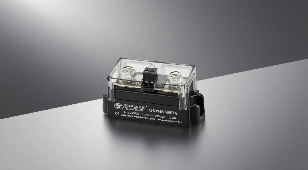
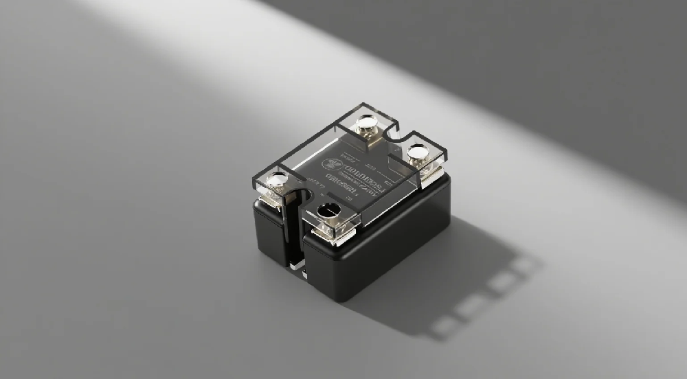
Solid-state relays (SSRs) are fully electronic devices consisting of three main parts:
1. Input circuit: Typically consists of an LED and current-limiting resistor, receiving control signals (commonly DC 3-32V)
2. Isolation circuit: Uses optocouplers or transformers to achieve input-output electrical isolation (withstand voltage of 2500-5000V)
3. Output circuit: Power switching devices (MOSFET, TRIAC, IGBT, etc) Working principle: Input voltage drives the LED to emit light → photosensitive device receives the light signal → triggers the power switch to conduct, realizing "electric-optical-electric" conversion and control. I. Current Calculation and Load Characteristic Analysis 1. Resistive loads (heaters, incandescent lamps, etc) Rated current calculation: Single-phase: I = P/220 or I = P/380 Three-phase: I = P/(380/√3) Considering various load conditions such as ambient temperature and heat dissipation, we recommend: Select current rating between 
1.4 to 2 times the resistive load's rated current.
2. Motors Rated current calculation: Single-phase motor: I = P/(220×0.85) (power factor) Three-phase motor: I = P/(380×√3×0.85) Starting current of motors is typically 5-7 times the rated current. II. Key Parameters for Product Selection Parameter Selection Guidelines Typical Range Load voltage Must cover actual operating voltage with safety margin 24-480VAC/60-100VDC Load current Calculate as per Section II with derating consideration 1-150A Control voltage Match control system output DC3-32V/AC90-280V Turn-on time Important for high-frequency applications 0.1-10ms Turn-off time Required for rapid switching applications 0.5-15ms Insulation voltage Industrial applications should be >2500VAC 1500-5000VAC Mounting method Choose based on heat dissipation conditions DIN rail/screw/heat sink III. Environment and Heat Dissipation 
1. Temperature impact: Derate above 40°C, must use heat sink for >10A, forced air cooling required for >100A. Soldering temperature should be <250°C for <10 seconds.
2. Mounting requirements: Apply thermal grease to heat sink surface and secure tightly for proper contact. IV. Protection Measures
1. Overvoltage protection: Recommend parallel connection of MOV or TVS protection.
2. Overcurrent protection: Requires series connection of fast-acting fuse, inductive loads should add RC snubber circuit. V. Other Considerations 1. AC output SSRs should not be paralleled. DC output SSRs can be paralleled to increase total current carrying capacity. 2. SSR outputs should not be series connected.
3. AC output SSRs should not be used with DC loads. AC output SSRs typically use TRIACs as power switches, which are current-zero self-turn-off devices and can only operate under AC voltage (current) conditions. VI. Selection Checklist 1. Are load type and current characteristics clearly defined? 2. Does calculated current include safety margin? 3. Has ambient temperature been considered for derating? 4. Do control signal parameters match?
5. What is the mounting method (PCB/rail/panel)?
6. Are installation space and heat dissipation conditions sufficient?
7. Are additional protection circuits required? 8. What are the certification requirements (UL/CE/CQC, etc.)?